Motorizing the summer-house valve with four transistors
My family's summer house has an outdoor garden tap, fed through a manual shutoff valve.
That valve lives at the bottom of a hole, about half a metre down, in the furthest corner of the workshop, under a shelf.
Reaching it means clearing the shelf, getting down on the floor, and putting an arm into the ground. So every spring I dig it out to open the tap, and every autumn I do it again to close it and drain the line before the frost. A pipe full of standing water and a Swedish winter have strong opinions about each other.
I want to replace it with a motorised valve I can throw from a switch indoors.
What it actually needs to do
The requirement is modest, and it's entirely about my back: shut the water off, open it again, without crawling under the shelf.
The freeze protection is still just shut it off and drain the line — no clever sensing or scheduling. The only thing that changes is doing it standing up indoors instead of head-down in a hole in the floor.
Closing it from the city before a cold snap would be nice. That's a later log. For now the whole interface is one switch on the wall.
The valve, and a deliberately silly decision
The valve is a CWX-15Q motorised ball valve — a ball valve with a geared motor on top — wired for the CR05 control scheme.
The thing to get straight is how it turns. It's a ball valve, so a quarter turn of the ball takes it from open to closed. And the motor only ever runs one way — it can turn indefinitely, so there's no reason to reverse it. You just keep driving it in the same direction and the valve cycles: open, closed, open, closed, a quarter turn at a time.
CR05 is the five-wire variant. Two wires power the motor. The other three are the limit switches — two signal wires sharing a common. One closes onto the common when the valve lands on fully open, the other when it lands on fully closed.
And here's the part that matters: the motor never stops on its own. There's no internal cutoff and nothing for it to bump against — leave power on and it keeps spinning, straight past the position you wanted and on toward the next one. The only things that mark "open" and "closed" are those two limit switches. So something external has to watch them and cut the power the instant the right one closes onto the common.
The sensible way to command this is an ESP32 and twenty lines of firmware. I didn't do the sensible thing.
I wanted to drive it from a single ordinary switch using nothing but discrete transistors. No microcontroller. No firmware to reflash at a cabin three hours from the nearest oscilloscope. Just a circuit that's either right or wrong and stays that way.
Mostly I did it because it sounded like fun — which is the only justification a hobby project really owes anyone.
One switch, and a circuit that knows when to stop
So the circuit doesn't have to think about direction at all — the motor only goes one way. Its only real decision is whether to be running. The switch sets the target: open or closed. The circuit runs the motor until the limit switch for that target closes onto the common, then cuts the power and leaves it there.
Flip the switch to the other state and it starts the motor again — same direction as always — and lets it run the next quarter turn until the other limit switch trips. Four transistors are enough to hold that little scrap of logic: run, watch the right limit, stop.
| Switch position | Target | Motor runs (one direction) until… |
|---|---|---|
| On | open | the open limit switch closes onto the shared common |
| Off | closed | the closed limit switch closes onto the shared common |
Parts so far — short, because it's still a breadboard:
| Part | Qty | Notes |
|---|---|---|
| CWX-15Q motorised ball valve (CR05) | 1 | single-direction motor, two power wires; two limit switches on a shared common; runs until power is cut |
| Transistors | 4 | run the one-way motor to the switch's target, then cut power at that limit switch |
| Switch | 1 | ordinary wall switch, lives indoors |
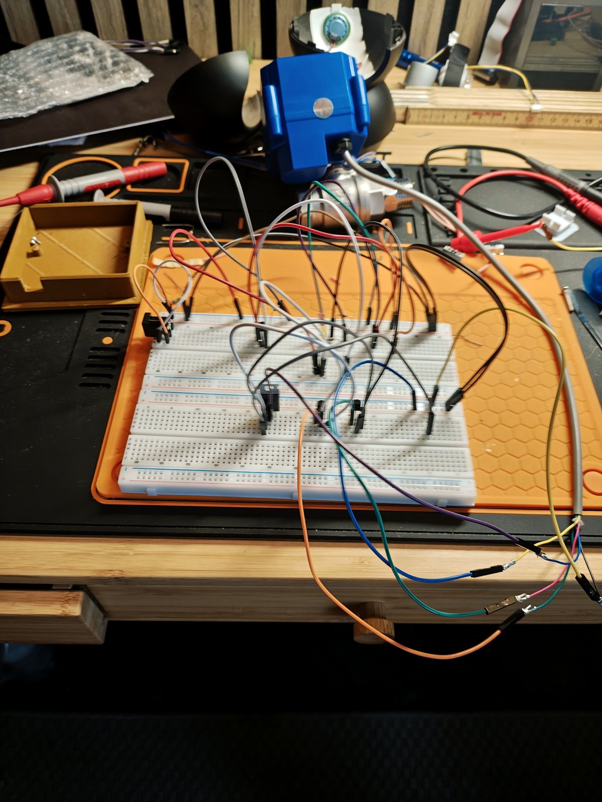
| Breadboard + jumpers | 1 | prototype only |
Right now it lives on a breadboard, and it works. Flip the switch one way and the valve drives open and stops; flip it back and it drives closed and stops. The transistors catch the limit switches and kill the motor at each end, which is the whole trick.
Caveat: a breadboard on the bench has never met a Swedish January. None of this has been near actual cold, or actual water, yet.
What's next
Get it off the breadboard and onto something permanent — perfboard or a small PCB — in an enclosure that can survive being mounted near plumbing.
Then install it at the summer house, with the switch somewhere I can reach standing up.
Once that earns its keep, the tempting next step is Wi-Fi, so I can close the valve remotely before a cold snap. But I'm not allowed to do that until the dumb version has survived at least one winter.